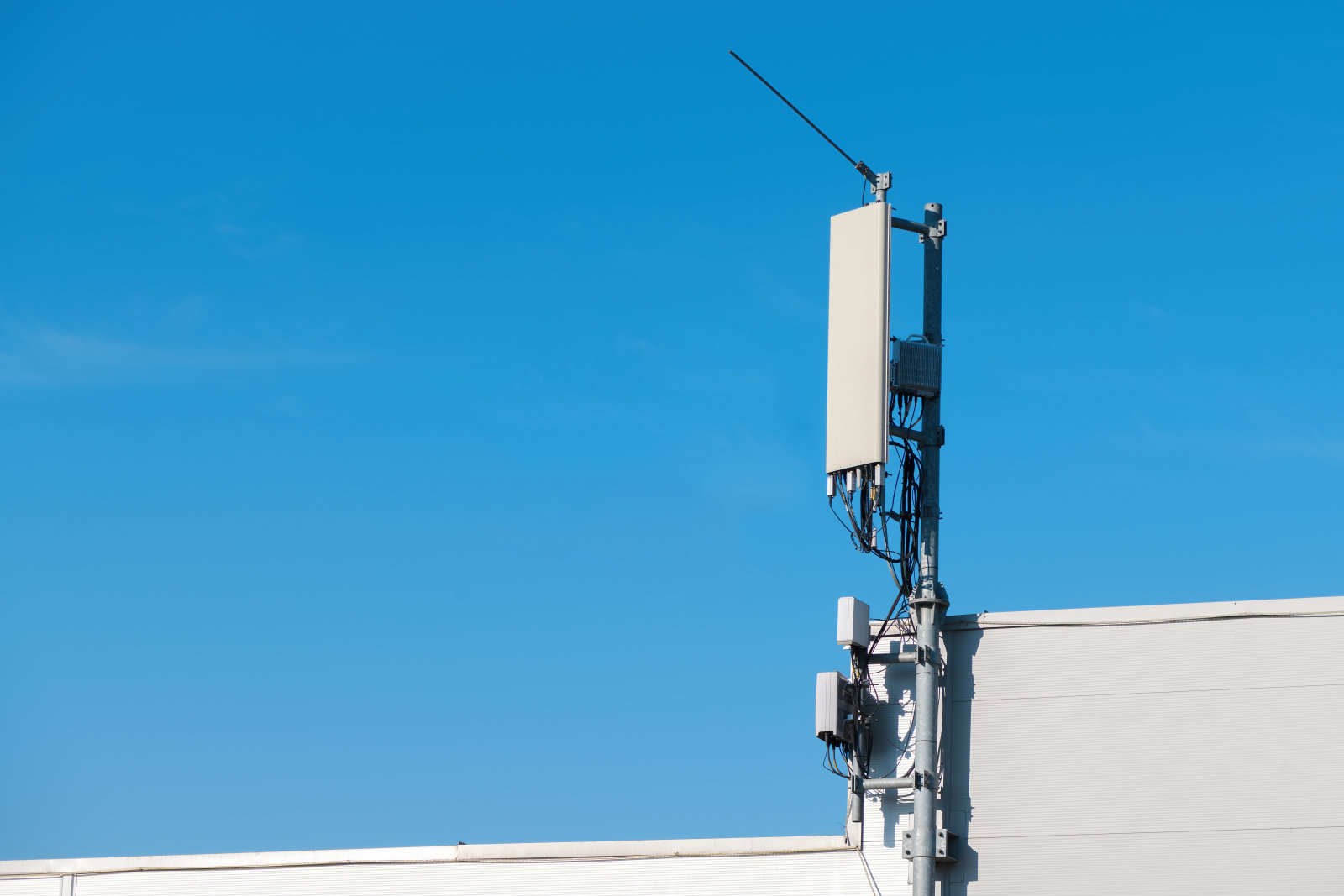
Directional couplers are passive devicesused mostly in the field of radio technology. They couple a signal in the main line to a port enabling the signal to be used in another circuit. An essential feature of directional couplers is that they only couple power flowing in one direction. Power entering the output port is coupled to the isolated port but not to the coupled port. A directional coupler designed to split power equally between two ports is called a hybrid coupler.
Coupler Ratio
Coupling ratio is defined as the ratio of output power to input power. By convention, the amplitude ratio is defined by the lower of the two output powers. Thus, a 90:10 split would imply a coupling ratio of 10 dB and a 99:1 split would imply a coupling ratio of 20 dB.
Coupler isolation
Coupler isolation measures the ratio between input power and power leakage from the isolated port. Typical values are 30-40 dB
Directivity
Directivity is an important figure because it measures the ability of a directional coupler to distinguish between signals traveling in opposite directions. The higher the directivity, the better the coupler can distinguish between forward traveling and backward traveling waves.
How to choose a Directional Coupler at lower cost
There is no need to specify a number of tight spec parameters when you need a power Directional Coupler for a particularly stringent requirement. For example, achieving a large bandwidth with excellent isolation is always accompanied by increases in circuit loss and overall size. Contrastingly, extremely broadband devices can be made in very small packages, but only at the expense of insertion loss and isolation.
In some applications, it is possible for several parameters to be important. In other applications, only one parameter may be considerably significant while others are not. You can lower your demands, and your cost, by analyzing what parameters must be met while understanding others that can be ignored.
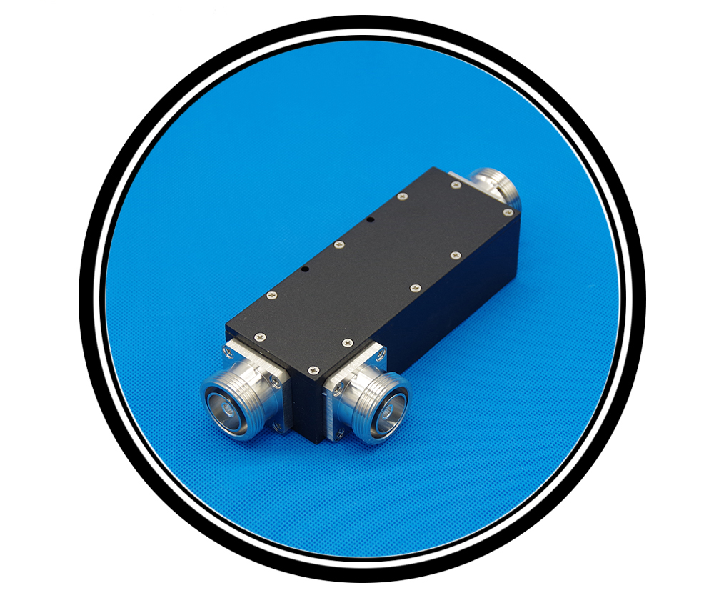
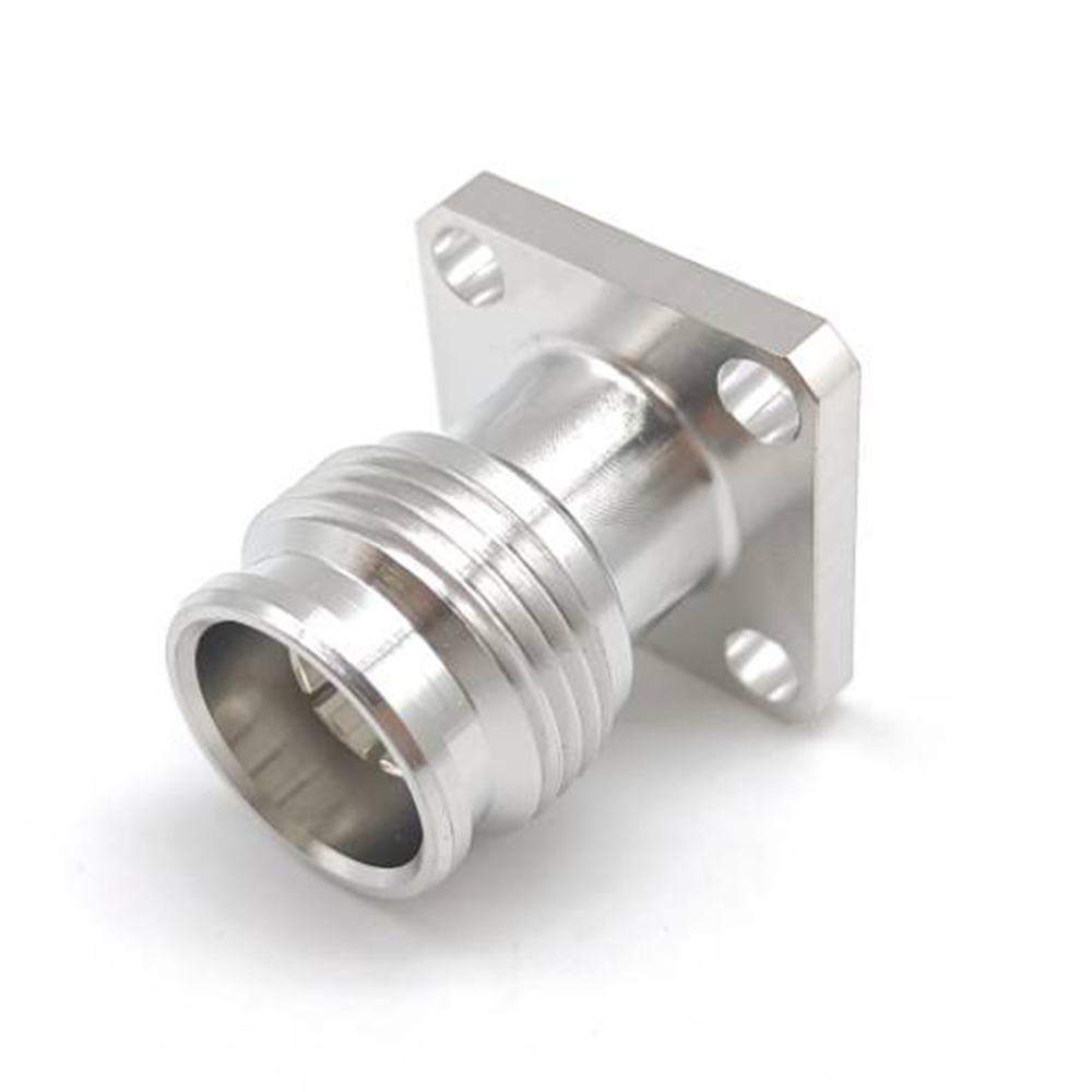
 Why is 4.3-10 Connector so popular
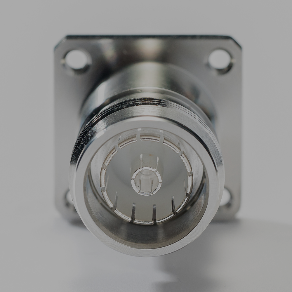
 What is RF Coaxial Connector